Arduino Autoclicker
"The Clickotron-5000"
Overview
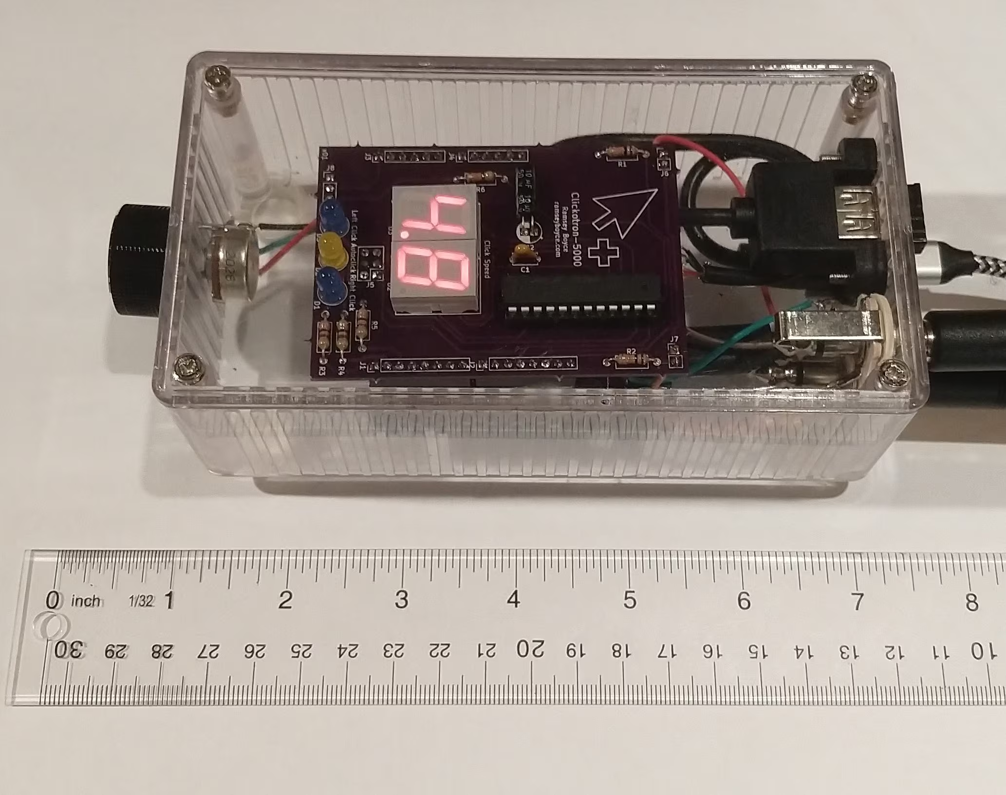
The Clickotron is an Arduino Leonardo shield designed to extend mouse capabilities. The full Clickotron-5000 autoclicking device uses an Arduino Leonardo, a USB Host Shield, and the Clickotron board running custom firmware.
By simulating mouse inputs, the device lets external switches trigger clicks. For example, I use two foot pedals for left and right clicking, with support for continuous autoclicking when held down. I built it to alleviate hand numbness from poor posture (since resolved) and still use it to play games with friends.
Link to the code: https://github.com/rmboyce/arduino-autoclicker
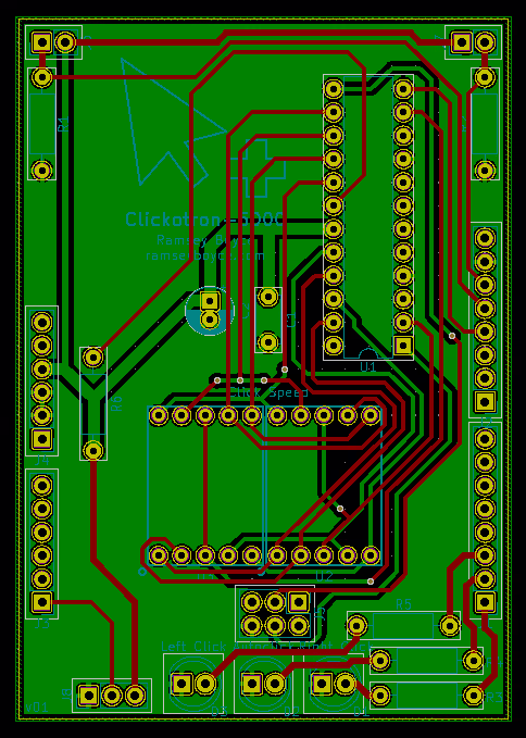
Link to the schematic: Autoclicker schematic
About the Device
A standard USB mouse plugs directly into the USB Host board, passing signals through so it behaves normally (see footnote 1). External switches can be wired to the Clickotron to trigger inputs.
The device toggles between regular and autoclick modes by holding both pedals down.
In regular mode, the pedal simulates a click for as long as it is pressed. Indicator LEDs light up during clicks, allowing operations like text selection by holding the pedal down and dragging the mouse.
In autoclick mode, holding a pedal clicks continuously. The click speed is set via a potentiometer and shown on a two-digit seven-segment display. Click intervals follow a normal distribution to mimic human clicking.
Usage
Assemble the circuit on the Clickotron PCB or a breadboard. If using normally-open switches, modify the code to trigger on HIGH instead of LOW. Load the program onto your Arduino Leonardo (ensure the "USB Host Shield Library 2.0" is installed via the Library Manager). If using an unconfigured USB Host Shield, bridge the 5V pad and the SPI lines to enable power and data transfer.
Note on scroll wheel issues: If the scroll wheel only works while the mouse is moving, edit `hiduniversal.h` in the USB Host Shield library and add `virtual` before the `bool BuffersIdentical` function on line 60.
One place to buy the USB Host board: https://shop.tkjelectronics.dk/product_info.php?products_id=43
USB Host hardware manual: https://chome.nerpa.tech/usb-host-shield-hardware-manual/
USB Host library documentation: https://github.com/felis/USB_Host_Shield_2.0
Technical Details
Link to the schematic: Autoclicker schematic
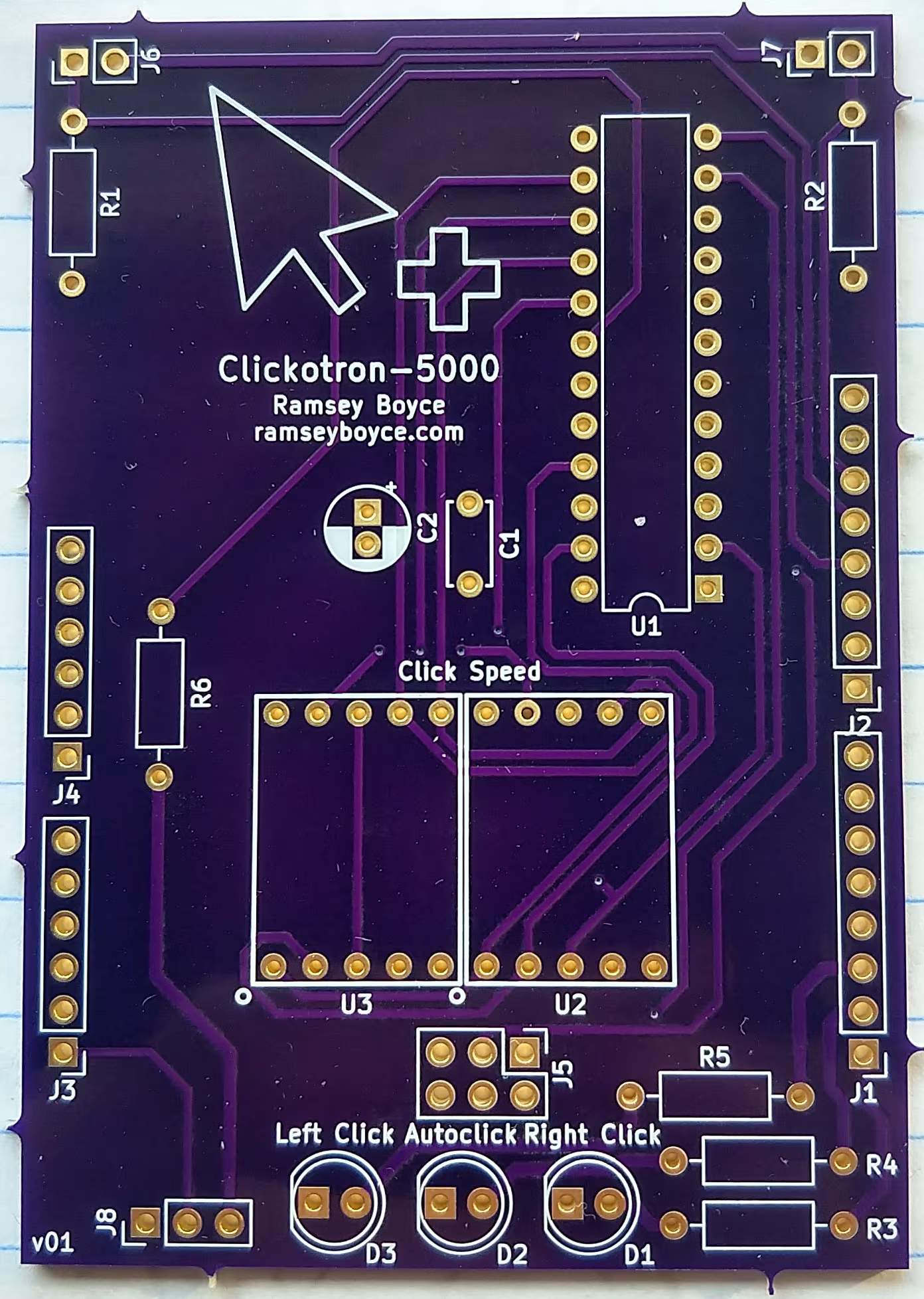
Closing a switch connects the input pin to 5V; opening it pulls the pin to ground via a 10 kΩ resistor. Since my foot pedals are normally closed (opening when pressed), the code triggers clicks on a LOW signal on pins 12 or 13.
The status LEDs are driven by digital output pins, protected by current-limiting resistors.
A potentiometer wired to pin A5 sets the autoclick speed.
A MAX7221 chip, controlled via SPI from the ICSP header, drives the two seven-segment displays. Capacitors C1 and C2 stabilize the power supply for the MAX7221, many sources note it as sensitive to power fluctuation.
Notes
The code works with standard USB mice. Complicated mice reporting non-standard inputs may require firmware modifications to format the HID reports correctly.